/Vehicles/Axis/Germany/02-mPanzers/PzKpfw4/File/2-Design.htm | Last Up-date:
Panzerkampfwagen IV Medium Tank
Design: Front Compartment
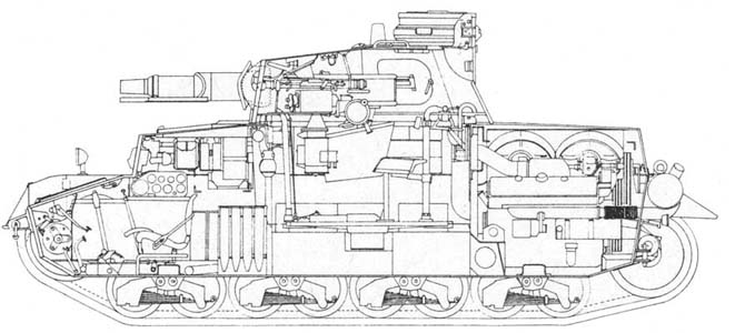
La caisse du Panzer IV présentait un design assez simple. Deux cloisons divisaient la caisse en trois compartiments: pilotage, combat et moteur. A l'avant le compartiment du pilote accueillait les ensembles de transmission et la commande finale, ainsi que les sièges du pilote et de l'O.R. (Opérateur Radio) qui se chargeait également de la mitrailleuse de caisse montée sur rotule (absente des modèles B/C).
The hull of Panzer IV presented a rather simple design. Two partitions divided the hull into three compartments: piloting, combat and engine. In front, the compartment of the pilot accomodated the sets of transmission and the final command, as well as the seats of the pilot and the R.O. (Radio Operator) which also took care of the machine-gun of hull assembled on ball (absent from models B/C).
 |
Panzer IV
Ausf.D interior details |
src: Connaissance de l'Histoire (Hachette),
n°17
|
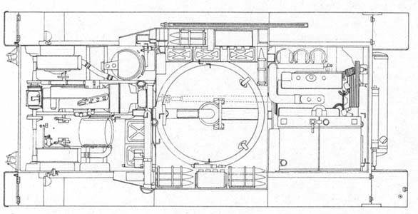
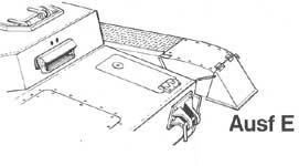
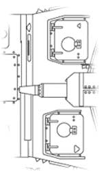
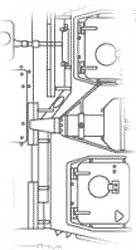
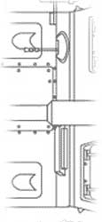
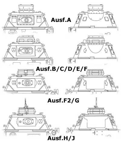
L'une des grandes caractéristique du Panzer IV est sa superstructure en porte-à-faux. En effet cette superstructure ou caisse supérieur, boulonnée sur le bossage supérieur de la caisse (inférieure ou bas de caisse), débordait largement sur les surplombs des chenilles afin de pouvoir accueillir la large circulaire de la tourelle. Cependant à l'avant de la superstructure, les parois latérales convergent, la superstructure n'a donc pas la même largeur partout. Sur le glacis à l'avant on trouvait trois trappes d'accès dont la centrale était boulonnée et encastrée (transmission) et les latérales montées sur charnière (freins). Les trappes d'accès (montées sur charnières) du pilote et de l'O.R. était situé sur le toit de la superstructure (ces plaques furent à deux ou un seul tenant selon les modèles) et celles-ci étaient protégées par des rails ainti-éclats. Sur les côtés de la superstructure on trouvait de chaque côté un sabord de vision avec vitre blindée interne et clapet blindé externe (ces sabords disparaîtront sur le dernier modèle l'Ausf.J) . La plaque frontale de la superstructure fut de deux type: le premier présentait une saillie au niveau du pilote sur la gauche (Ausf.A/D/E) alors que le second présentait une surface parfaitement plate (Ausf.B/C/F/F2/G/H/J). Sur cette plaque on trouvait à gauche le viseur du pilote (plusieurs modèles seront montés: à double ou unique clapet) et à droite la MG 34 montée sur rotule.
One of large the characteristic of Panzer IV is its cantilever superstructure. Indeed this superstructure or upper hull, bolted on the upper embossing of the hull (lower hull), overflowed largely on the overhangs of the tracks in order to be able to accomodate the broad circular of the turret. However in front of the superstructure, the side walls converge, the superstructure thus does not have the same width everywhere. On the glacis in front one found three access hatches whose the middle hatch was bolted and embedded (transmission) and the side hatches mounted on hinge (brakes). Access hatches (mounted on hinges) of the pilot and the R.O. was located on the roof of the superstructure (these plates were with two or only one pieces according to models) and those were protected by rails anti-glares. On the sides of the superstructure one found each side a port of vision with armoured intern glass and external armoured valve (these ports will disappear on the last model Ausf.J). The frontal plate of the superstructure was two type: the first presented a bulge (pilot station) on the left (Ausf.A/D/E) whereas the second had a surface perfectly punt (Ausf.B/C/F/F2/G/H/J). On this plate one found on the left the visor of the pilot (several models will be ridden: with double or single valve) and on the right the MG 34 mounted on ball.
 |
Panzer IV
Ausf.D interior details |
src: Connaissance de l'Histoire (Hachette),
n°17
|
 |
Panzer IV
Ausf.D interior details |
src: Connaissance de l'Histoire (Hachette),
n°17
|
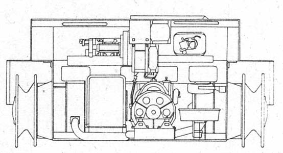
La puissance du moteur était transmise, par l'intermédiaire d'un arbre de transmission et d'un embrayage sec à trois plateaux, à une boîte de vitesse à six rapports synchronisés. De petits embrayages multi-disques de synchronisation étaient utilisés pour les 2e, 3e, 4e, 5e et 6e vitesses. Le Panzer IV était équipé d'un commande finale et d'un mécanisme de direction Krupp-Wilson du type "embrayage-frein". Dans ce dernier l'engrenage d'entrée entraînait la couronne du train épicycloïdal. La roue-soleil était couplée au tambour de frein de direction, qui était maintenu immobile quand le char était en mouvement par une frette externe et un ressort à compression. Le mouvement provenant de la couronne épicycloïdalétait transmis via le porte-satellite aux engrenages cylindriques de réduction qui entraînaient les barbotins des chenilles. La boîte de vitesse à 6 rapports et les ensembles de commande finale avaient en commun un seul système de circulation d'huile.
The engine output was transmitted, by means of a driveshaft and a dry clutch with three plates, to a gear box with six synchronized speeds. Small multidisk clutches of synchronization were used for 2nd, 3rd, 4th, 5th and the 6th speeds. Panzer IV was equipped with Krupp-Wilson final command and mechanism a steering of the type "clutch-brake". In this last the gears of entry involved the crown of the epicyclic gear. The wheel-sun was coupled with the brake drum of direction, which was maintained motionless when the tank was moving by an external hoop and a spring with compression. The movement coming from the epicycloidal crown was transmitted via the satellite carrier to the cylindrical gear of reduction which actuated the sprocket-wheels of the tracks. The gear box of 6 speeds and the sets of final command had in common only one system of oil circulation.
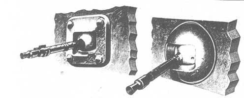 |
Les Panzers IV utilisèrent
deux types de montage sur rotule pour leur MG34 de caisse: à gauche: Kugelblende 30 (blindage de 30mm) pour MG34 monté sur les modèles A/D/E à droite: Kugelblende 50(blindage de 50mm) pour MG34 monté sur les modèles F-J |
Panzers
IV used two types of ball mount for their MG34 of hull: on the left: Kugelblende 30 (armor of 30mm) for MG34 assembled on the A/D/E models on the right: Kugelblende 50(armor of 50mm) for MG34 assembled on the F-J models |
src: Connaissance de l'Histoire (Hachette),
n°17
|
 |
 |
Panzer IV
Ausf.D interior details |
Driver's visor |
src: Connaissance de l'Histoire (Hachette),
n°17
|
src: Pz.Kpfw IV in action, Armor Number 12 (squadron/signal
publications, inc.)
|
La transmission coupait le compartiment en deux dans le sens de la longueur. A gauche on trouvait le siège du pilote et à droite celui de l'O.R. situé plus en arrière. La transmission était légèrement décalé vers la droite rendant le poste de l'O.R. très étroit, ce qui explique la position très en arrière du siège, là ou la transmission est la moins large. Le poste radio et le tableau de bord étaient montés sur la transmission et séparaient un peu plus les deux hommes. Derrière le siège du pilote on trouvait un grand coffre à munitions de 75. Sur la plaque frontale du bas de caisse (du nez) était monté un double système d'arrimage pour câble de remorquage. Notons encore que selon les modèles un ou deux phares seront montés sur l'avant des surplombs des chenilles.
The transmission divided the compartment in two in the length. On left one found the seat of the pilot and on the right that of the R.O. located behind. The transmission was slightly shifted towards the right and the R.O. station was very narrow, which explains the position very behind of the seat, there or the transmission is the least broad. The radio station and the dashboard were assembled on the transmission and separated a little more the two men. Behind the seat of the pilot one found a large box with ammunition of 75. On the frontal plate of the lower hull (nose) a double system of stowing for cable of towing was assembled. Still let us note that according to models one or two headlights will be assembled in front of overhangs of the tracks.
 |
Panzer
IV Ausf.A front deck |
src: Vincent Bourguignon
|
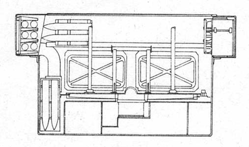
Le compartiment de combat était en grande partie du plancher de tourelle circulaire qui était rattaché à cette dernière par des tubes métalliques. Sur ce plancher se trouvait le système électrique de rotation de la tourelle couplée à un moteur deux temps dont on aperçoit le silencieux d'échappement à l'arrière du char (cylindrique ou rectangulaire). Sur l'Ausf.J la rotation se faisant manuellement tout cet appareillage fut supprimé.
The compartment of combat was mainly circular floor of turret which was attached to the latter by metal tubes. On this floor the electric system of rotation of the turret coupled to a two-stroke engine was which one sees the exhaust box to the back of the tank (cylindrical or rectangular). On Ausf.J rotation being made all this equipment manually was removed.
 |
 |
 |
Panzer IV
Ausf.B/C front deck |
Panzer IV
Ausf.D front deck |
Panzer IV
Ausf.F/F2/G/H/J front deck |
src: Vincent Bourguignon
|
||
Sous le plancher était disposés les 3 réservoirs d'essence accueillant les 470 litres de carburant embarqués. Sur le côtés droit du bas de caisse étaient disposés 3 râteliersà munitions de 75. Deux coups de 75 étaient également fixés au mur anti-feu du moteur. Le reste étant rangé dans des râteliers protégés par un simple toile sur les surplombs des chenilles dans la superstructure. Sur le côté droit de la superstructure étaient également rangés les cartouchières des MG 34.
Under the floor was laid out the 3 tanks of gasoline accomodating the 470 liters of fuel load. On the right side of the lower hull 3 racks for 75 ammo were laid out. Two rounds of 75 were also fixed at the fire-resistant wall of the engine. The remainder being arranged in racks protected by a simple fabric on the overhangs of the tracks in the superstructure. On the right side of the superstructure the cartridge pouches of the MG 34 were also arranged. The battery of the tank was installed with the right of the driving shaft very near of the firewall of the engine.
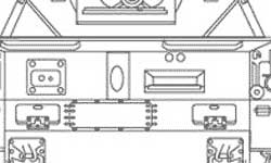 |
Panzer IV
Ausf.E front plate |
src: Vincent
Bourguignon |
La tourelle soudée accueillait les sièges du chef de char, du tireur et du chargeur. Les côtés étaient inclinés de telle sorte que la largeur hors-tout était supérieur au diamètre intérieur de la circulaire de tourelle. Le canon de 75 était monté sur un axe à tourillons. L'extrémité avant du mécanisme de recul dépassait du masque pour assurer une protection supplémentaire. La coupole du commandant montée à l'arrière de la tourelle comportait cinq fentes de vision. Cette coupole était fermée par deux capots de trappe semi-circulaire. Une fente d'observationétait aménagée de chaque côté de la tourelle (supprimée dès l'Ausf.G) devant les trappes d'accès latérales (double ou porte unique). Ces portes comportaient également une fente de vision avec clapet blindé et pour le modèle à deux portes un sabord de tir au pistolet (la fente et le sabord seront supprimés sur l'Ausf.J). Des sabords de tir au pistolet étaient également présents à l'arrière de la tourelle mais disparaîtront dès l'Ausf.G. A l'avant deux fentes d'observation protégés par un clapet assuraient une vision frontale au tireur et au chargeur. Celle du chargeur sera supprimée sur les modèles H/J.
The welded turret accomodated the seats of the head of tank, the gunner and the loader. The sides were tilted so that the overall width was higher than the internal diameter of the ring of turret. The gun of 75 was assembled on an axis with pivots. The front end of the mechanism of retreat exceeded mask to ensure an additional protection. The cupola of the commander mounted to the back of the turret comprised five slits of vision. This cupola was closed by two semicircular caps of hatch. A slit of observation was arranged on each side of the turret (removed on Ausf.G) in front of the side access hatch (double or single pieces). These hatches also comprised a slit of vision with armoured valve and for the model with two pieces a port of pistol shooting (the slit and the port will be removed on Ausf.J). Ports of pistol shooting were also present on the back of the turret but will disappear as of Ausf.G. On front platen two slits of observation protected by a valve ensured a frontal vision to the gunner and the loader. That of the loader will be removed on models H/J.
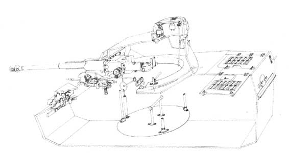 |
Panzer IV
Ausf.F2 weapons system |
src: Connaissance de l'Histoire (Hachette),
n°17
|
Une tape de signalisation était montée sur le toit de la tourelle semblable à celles présentes sur les trappes du pilote et du O.R. Le compartiment de combat était aéré par un ventilateur situé sur le toit rejetant l'air vicié à l'extérieur.
A signal slap was mounted on the roof of the turret similar to those present on the trap doors of the pilot and the R.O. The compartment of combat was aired by a ventilator located on the roof rejecting the foul air outside.
75
mm KwK 37 L/24 Penetration of a shielding plate (mm) under a plunging angle of 30° |
|||||||
Ammo
|
Weight
|
Velocity
|
100
m |
500
m |
1000
m |
1500
m |
2000
m |
| K Gr rot Pz | 6.8 kg |
385 m/s |
41 |
39 |
35 |
33 |
30 |
| Gr 38 H1/A | 4.4 kg |
450 m/s |
70 |
39 |
35 |
33 |
30 |
| Gr 38 H1/B | 4.57 kg |
450 m/s |
75 |
39 |
35 |
33 |
30 |
Gr 38 H1/C |
4.80 kg |
450 m/s |
100 |
39 |
35 |
33 |
30 |
75
mm KwK 40 L/43 Penetration of a shielding plate (mm) under a plunging angle of 30° |
|||||||
Ammo |
Weight |
Velocity |
100
m |
500 m |
1000
m |
1500 m |
2000
m |
| PzGr 39 | 6.8 kg |
740 m/s |
98 |
91 |
82 |
72 |
63 |
| PzGr 40 | 4.1 kg |
920 m/s |
126 |
108 |
87 |
69 |
- |
75
mm KwK 40 L/48 Penetration of a shielding plate (mm) under a plunging angle of 30° |
|||||||
Ammo |
Weight |
Velocity |
100
m |
500 m |
1000
m |
1500 m |
2000
m |
| PzGr 39 | 6.8 kg |
790 m/s |
106 |
96 |
85 |
74 |
64 |
| PzGr 40 | 4.1 kg |
990 m/s |
143 |
120 |
97 |
77 |
- |
 |
Turret development
|
src: Vincent Bourguignon
|
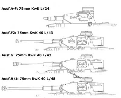
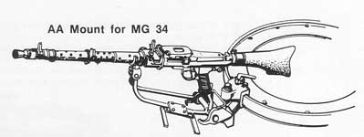
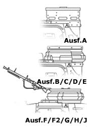
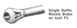
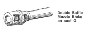
Le canon d'origine était le 75 mm KwK 37 L/24 court à faible vitesse initiale prévu initialement pour un char de support et la destruction des armes anti-char ennemie et non la lutte char contre char. Le Panzer IV prenant de plus en plus un rôle de véritable char de bataille, ce canon devint vite obsolète face au blindage des chars ennemis (KV-I et T-34/76). Un canon à haute vitesse initiale était devenu primordiale et le tube fut allongé pour procurer cette grande vitesse nécessaire pour percer les blindages. Le premier modèle de canon de 75 à tube long fut le KwK 40 L/43 qui fut utilisé avec deux type de frein de bouche (avec unique (Ausf.F2) ou double déflecteur (Ausf.G)). Sur les derniers modèles (Ausf.H/J) sera monté un canon de 75 avec un tube encore plus long, le KwK 40 L/48 (avec frein de bouche à double déflecteur) procurant une vitesse initiale encore plus élevée. Ce canon était accompagné à sa droite d'une MG 34 coaxiale. Sur la coupole des derniers modèles, on pouvait installer une MG 34 anti-aérienne sur un montage spéciale.
The gun of origin was the short 75 mm KwK 37 L/24 at low initial speed planned initially for a tank of support and the destruction of the enemy anti-tank weapons and not the fight tank against tank. Panzer IV having more and more a role of genuine tank of battle, this gun quickly became obsolete against the shielding of the enemy tanks (KV-I and T-34/76). A gun with high initial speed had become paramount and the tube was lengthened to get this high speed necessary to bore the shieldings. The first model of gun of 75 with long tube was KwK 40 L/43 which was used with two type of muzzle breaks (with single (Ausf.F2) or double deflector (Ausf.G)). On the last models (Ausf.H/J) a gun of 75 with a tube even longer will be assembled, KwK 40 L/48 (muzzle break with double deflector) getting an initial speed even higher. This gun was accompanied on its right by a MG 34 coaxial. On the cupola of the last models, an anti-aircraft MG 34 could be installed on an special mount.
 |
75 mm gun
development |
src: Vincent Bourguignon
|
 |
Ring mount
of the commander's cupola |
src: Pz.Kpfw IV in action, Armor Number 12 (squadron/signal
publications, inc.)
|
 |
|
Commander's
cupola develoment |
Muzzle
brake develoment |
src:
Vincent Bourguignon |
src: Pz.Kpfw IV in action,
Armor Number 12 (squadron/signal publications, inc.) |
 |
_Inside.jpg) |
Smoke
grenades launchers |
Turret
doors (late model) |
src: Pz.Kpfw IV in action, Armor Number 12 (squadron/signal
publications, inc.)
|
|
Sources:
- Pz.Kpfw IV in action, Armor Number 12 (squadron/signal publications, inc.)
- Connaissance de l'Histoire (Hachette) - N°17 - " Les chars de combat allemands 39-45"
- Connaissance de l'Histoire (Hachette) - N°5 - " Véhicules blindés allemands 39-45"
- Les Blindés de la Seconde Guerre Mondiale (Atlas)
- Panzerkampfwagen IV Medium Tank 1936-1945 (Osprey Military) - New Vanguard N°28
- Site "Achtung Panzer" - http://www.achtungpanzer.com
- Site "Germany's vehicle history" - http://www.wwiivehicles.com
- Site "Second World War Armour" - http://www.onwar.com/tanks/index.htm